How does the Venturi System Work?
A Venturi System reduces pressure when a fluid flows through a constricted section (or choke) of a pipe. In 1797, Giovanni Battista Venturi performed experiments on flow in a cone-shaped tube and built the first flowmeter for closed pipes called the “Venturi tube”. A Venturi vacuum is created by a pump with compressed air running through it, yet the pump has no moving parts. Compressed air runs through the initial chamber, then a smaller portal that opens into another larger chamber, which is like the first one.
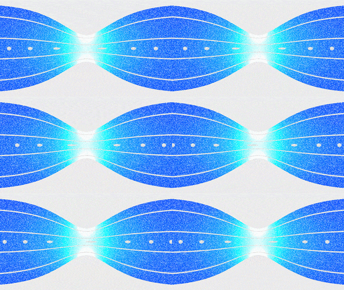
The static pressure in the first measuring tube (1) is higher than at the second (2), and the fluid speed at “1” is lower than at “2”, because the cross-sectional area at “1” is greater than at “2”.https://en.wikipedia.org/wiki/Venturi_effect
Constricting a pipe where fluid flows through results in lower pressure. This principle is counter intuitive to common sense. Why does the pressure decrease? Where does the fluid go if the pathway is constricted? When fluid starts to flow, its velocity around the orifice in the pipe increases significantly because of the restriction in the cross-section. An illustration of this is water flowing through a pipe. Water is a liquid that is not easily compressed. When the water flows through the constricted region of a pipe, the water flows faster. The same volume of water must pass through the same space quicker. The smaller the constricted region of the pipe is compared to the original radius, the faster the speed of the fluid.
The faster the moving fluid, the lower the pressure (i.e. Bernoulie’s principle) and the higher the velocity, the greater the difference in differential pressure measured. Abrupt restrictions generate severe turbulence in a fluid. Adding a nozzle that are suited for higher flow velocities to fluids with abrasive particles will reduce turbulence and creates less pressure loss. Turbulence reduction is greater with Venturi nozzles and tubes where the restriction is created by longer, conical constrictions in the pipe wall.
NOTE: The longer the exhaust section of the pipe, the stronger the vacuum effect.
All Venturi systems, including gauges, meters, nozzles, orifice plates, chokes, and pipes can be supplied with different restriction diameter sizes so that the pressure loss and differential pressure generated can be optimized for the process conditions and applications. “In fluid dynamics, an incompressible fluid’s velocity must increase as it passes through a constriction in accord with the principle of mass continuity, while its static pressure must decrease in accord with the principle of conservation of mechanical energy” (Wikipedia, Venturi effect, Retrieved on September 18, 2018). Therefore, any gain in fluid kinetic energy and velocity as it flows through a restriction is balanced by a drop-in pressure.
Interesting note: The mass flow rate for a compressible fluid will increase with increased upstream pressure, which will increase the density of the fluid through the constriction (though the velocity will remain constant). This is the principle of operation of a de Laval nozzle. Increasing source temperature will also increase the local sonic velocity, thus allowing for increased mass flow rate but only if the nozzle area is also increased to compensate for the resulting decrease in density.
The Venturi system consists of:
- Venturi Vacuum Switch or Nex Flow Ring Vac®
- Hose or pipe
- Minimum 2.5 CFM @ 90 PSI
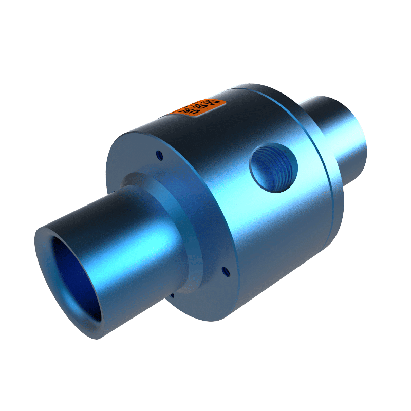
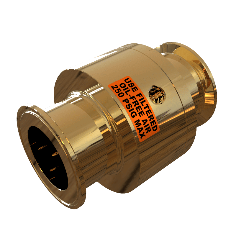
The Venturi system increases the sucking capacity of any air compressor. To configure a Venturi Vacuum, plug the compressor into one end, move the switch to the vacuum setting, and plug the other end into a vacuum device.
The main component is a Venturi tube. As fluid flows through a length of pipe of changing diameter. To avoid undue aerodynamic drag, a Venturi tube typically has an entry cone of 30 degrees and an exit cone of 5 degrees. (Wikipedia, Retrieved September 18, 2018).
Accessories
- Quick disconnect/connect nozzle fitting
- Pressure or vacuum gauges to monitor how much vacuum is created with the system
- Vacuum pump to collect material and then use the Venturi system to move the material a greater distance
Advantages of a Venturi Vacuum System
The best advantages of a Venturi Vacuum System is that it:
- Creates a high vacuum and amplified flow to generate a strong conveying force to move any material with ease.
- Reduces energy costs with less air consumption and uses less pressure.
- Less likely to contaminate air flow because of the straight through design, which prevents clogging.
- Lightweight and portable; Simple configuration, which is easier to manufacture and less expensive to purchase. Quickly and easily assembled and attaches to existing configuration. Has no valves and requires no filters.
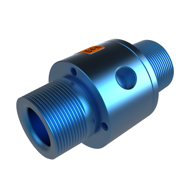
- Configurable: Standard, Threaded (NPT or BSP) or Flanged connection
- Available in a wide choice of materials: Anodized/hard anodized Aluminum, 304/316L stainless steel, and Teflon. Built to last: materials are treated to ensure longevity in the product’s life cycle
- Exceeds multi-stage pumps by 2 to7 times
- No electrical or explosion hazard
Venturi System Applications
Venturi tubes are used in processes where permanent pressure loss is not tolerable and where maximum accuracy is needed in case of highly viscous liquids. It is also used in applications where they replace electrically powered vacuum pumps:
- Gas venting
- Moving metal parts in a machinery rough environment:
- Hopper loading; Plastic pellets for injection molding
- Trim Removal
- Filling operations
- Material Transfer
- Sandblasting
- Gas through a transmission line or scrubber: Moves wet and dry material or fluid through a pipe
- Energy Transmission: Transporting solvents and chemicals, for example, oil and gas, steam
- Convert a standard air compressor into a suction machine to secure products with a uniform suction to secure a base to a surface. Using an air compressor as a clamping force also prevents the need for holes on a work surface.
- Measure the speed of a fluid, by measuring pressure changes at different segments of the device:
- Measure fuel or combustion pressures in jet or rocket engines
- Measure small and large flows of water and wastewater
- In metrology (science of measurement) for gauges calibrated for differential pressures.
- Water aspirators that produce a partial vacuum using the kinetic energy from the faucet water pressure
- Connect your vacuum bag to make vacu-formed laminates
- Vacuum forming operations for efficient industrial applications
- Atomizers that disperse perfume or spray paint (i.e. from a spray gun).
FEATURED PRODUCTS
What is a Vacuum Pump?
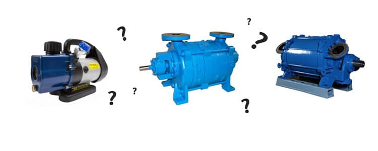
A vacuum pump is a device, which was invented in 1650 by Otto von Guericke. It removes air and gas molecules from a sealed or confined space, which results in a partial vacuum. Sometimes vacuum pumps remove gas from an area, leaving a partial vacuum behind or remove water from one area to another, such as a sump pump does in a basement.
The performance of a vacuum pump is measured on the speed of the pump or the volume of flow at the inlet in volume per unit of time. The pumping rate fluctuates for each type of pump and the gas/liquid/fluid that it is used on. The number of molecules pumped out of the container per unit of time or throughput is another performance factor.
A vacuum’s suction is caused by a difference in air pressure. A fan driven by an electricity reduces the pressure inside the machine. Atmospheric pressure then pushes the air through the carpet and into the nozzle so that the dust is literally pushed into the bag.
The components of a vacuum pump are:
- Suction: The higher the suction rating, the more powerful the cleaner.
- Input Power: The power consumption is in watts. The rated input power does not indicate the effectiveness of the cleaner, only the amount of electricity it consumes
- Output Power: The amount of input power is converted into airflow at the end of the cleaning hose. The airflow is often stated in airwatts (watts).
How does a Vacuum Pump Work?
A rotating shaft, in a sealed space, removes air and gas molecules. This action progressively decreases the air density within the enclosure resulting in a vacuum. As the pressure in the enclosure is reduced, it becomes more difficult to remove additional particles. The amount of energy produced by a vacuum pump depends on the volume of gas removed and the produced pressure difference between internal and external atmosphere.
The two technologies used by vacuum pumps are gas transfer or capture.
Transfer pumps allocate the thrust from the vacuum side to the exhaust side to accelerate the gas.
They move the gas molecules by kinetic action or positive displacement:
Kinetic transfer pumps direct the gas towards the pump outlet using high speed blades or introduced gas pressure. Kinetic pumps do not typically have sealed containers but can achieve high compression ratios at low pressures.
Positive displacement transfer traps gas and moves it through the pump. They are often designed in multiple stages on a common drive shaft. The isolated volume is compressed to a smaller volume at a higher pressure and expelled to the atmosphere (or to the next pump). It is common for two transfer pumps to be used in series to provide a higher vacuum and flow rate. The expelled gas is above atmospheric pressure when the same number of gas molecules exit the pump as enter it. The compression ratio is the exhaust pressure at the outlet measured in relation to the lowest pressure obtained at the inlet.
Capture pumps capture the gas molecules on surfaces within the vacuum system. This pump works at lower flow rates than transfer pumps but can provide a very strong vacuum. Capture pumps operate using cryogenic condensation, ionic reaction, or chemical reaction and have no moving parts. They can generate an oil-free vacuum.
The mechanical vacuum pumps usually have an electrical motor as a power source, but can alternatively rely on an internal combustion engine, and draw air from a closed volume and release it to the atmosphere. The rotating-vane vacuum pump is the most popular of kind of mechanical pump. Individual rotors are placed around a shaft and spin at high velocities. Air is trapped and moved through the intake port and a vacuum is created behind it.
Types of Vacuum Pumps
Pumps can be considered either wet or dry pumps, depending on whether or not the gas is exposed to oil or water during pumping. Wet pump will use oil or water for lubrication and/or sealing and this fluid can contaminate the swept (pumped) gas. Dry pumps have no fluid. They have tight spaces between the rotating and static parts of the pump, use dry polymer (PTFE) seals, or a diaphragm to separate the pumping mechanism from the swept gas. Dry pumps reduce the risk of system contamination and oil disposal compared to wet pumps.
Note: Vacuum pumps are not easily converted from wet to dry by changing the pump’s style. The chamber and piping can be contaminated if wet. Therefore, all wet pumps must be thoroughly cleaned or replaced, otherwise they will contaminate the gas during operation.
| Primary/Booster/Secondary | Name | Type of pump |
|---|---|---|
| Primary (Backing) pumps | Oil Sealed Rotary Vane Pump | Wet Positive Displacement |
| Liquid Ring Pump | ||
| Diaphragm Pump | Dry Positive Displacement | |
| Scroll Pump | ||
| Booster Pumps | Roots Pump | |
| Claw Pump | ||
| Screw Pump | ||
| Secondary Pump | Turbomolecular Pump | Dry Kinetic Transfer |
| Vapor Diffusion Pump | Wet Kinetic Transfer | |
| Cryopump | Dry Entrapment | |
| Sputter Ion Pump |
Reasons to use a Vacuum Pump:
- Provide a force
- Collect dust
- Remove active and reactive constituents
- Remove trapped and dissolved gases
- Decrease thermal transfer
- Increase the “mean free path” of gas molecules so that the pressure becomes useful.
The mean free path is the distance a molecule travels before colliding with another molecule. A molecule could experience the following types of flow in a vacuum:
- Viscous flow, turbulent: Tremendous random movement as the molecules try to move into any open space that may lead to a faster exit.
- Viscous flow, laminar: After a few minutes, the rush of molecules to leave ends and they begin to move to an exit in an orderly fashion.
- Molecular flow: The mean free path becomes longer inside the diameter of the pipe creating free flow of molecules. The gas molecules will more likely collide with the pipeline (container) walls than with another molecule. As the pressure drops the conductance also drops until the gas flow changes to molecular flow. Conductance is the measure of the mass of gas flowing at the average pressure per meter of the pipe length.
Advantages of a Vacuum Pump
- Moves large volume of air/low vacuum
- Converts pressure to flow (requires higher pressure to operate)
- Collects dirt, dust, and debris
- Saves energy
- Durable
Vacuum Pump Applications
- Medical processes, which require suction such as therapy or mass spectrometers
- Chemical and pharmaceutical applications
- Scientific analytical instruments that analyzes solid, gas, surface, liquid, and biological materials such as electron microscopy
- Process industries to vent fumes, remove dust and dirt, power equipment, and trash compacting:
- Sugar mills
- Pulp & paper
- Cement
- Vacuum tubes
- Electric lamps
- Semiconductors
- Glass coating
- Gyroscopes in flight instruments are powered by a vacuum source in case of an electrical failure.
- Treatment plants for sewage systems
- Remove water from one area to another, such as a sump pump does in a basement.
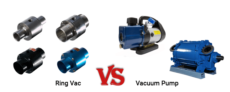
Venturi System VS Vacuum Pump
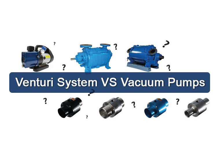
A Venturi system can be used in many of the same applications as a vacuum pump. The main advantage of Nex Flow’s Venturi system (Ring Vac) is that the units are compact and rugged, simple to configure and requires no maintenance compared to the vacuum pumps. When continuously venting air – choosing a low pressure vacuum pump can save energy costs. However – if intermittent conveying of materials is what you are looking for – a compressed air operated ring vac with an instant on/off switch can save energy cost when using compressed air.


